

Designing a Fiber-to-the-Home (FTTH) network is more than connecting an optical line terminal to a customer’s home. A reliable FTTH deployment requires careful planning of the OLT, Optical Distribution Network (ODN), optical splitters, and ONT, along with the physical routes and connectivity between them.
For Internet Service Providers (ISPs), these components determine how efficiently the network can be deployed, how many subscribers it can support, how much optical loss occurs across the network, and how easily the infrastructure can be maintained as the subscriber base grows.
A well-designed FTTH network therefore needs to consider both physical infrastructure and logical connectivity from the beginning.
What Are the 4 Key Components of an FTTH Network?
The four fundamental components are:
- Optical Line Terminal (OLT)
- Optical Distribution Network (ODN)
- Optical Splitters
- Optical Network Terminal (ONT)
Together, they create the end-to-end path that carries broadband services from the ISP network to the subscriber.
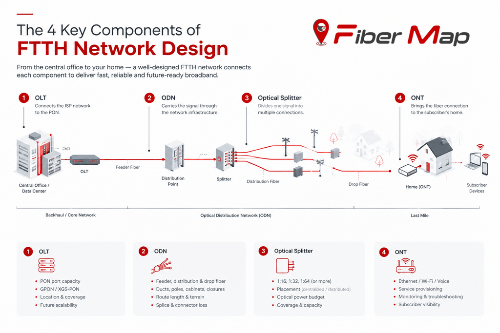
1. Optical Line Terminal (OLT)
The Optical Line Terminal (OLT) is the starting point of a PON-based FTTH network. It is typically located at the ISP’s central office, data center, or point of presence.
The OLT connects the ISP’s core or aggregation network to the passive optical access network. It manages communication with multiple ONTs or ONUs connected through the ODN.
During FTTH network design, ISPs need to consider:
- Number of PON ports required
- Expected subscriber count
- GPON, XGS-PON, or other PON technology
- Required bandwidth per subscriber
- OLT location and coverage area
- Future capacity and upgrade requirements
OLT capacity should therefore be planned around both current demand and expected subscriber growth.
2. Optical Distribution Network (ODN)
The Optical Distribution Network (ODN) is the physical fiber infrastructure between the OLT and the subscriber premises.
It includes several sections, commonly organized as:
OLT/ODF → Feeder Fiber → Distribution Point → Splitter → Distribution Fiber → Drop Fiber → ONT
The ODN can include fiber cables, optical distribution frames, fiber distribution terminals, closures, cabinets, access terminals, ducts, poles, and other passive infrastructure.
ODN design has a major influence on deployment cost and network performance. Route length, fiber count, splice points, connector losses, geographical conditions, and available infrastructure all need to be considered.
ITU-T optical access network guidance similarly separates FTTH infrastructure into feeder, distribution, drop, and customer-side sections.
For an ISP, simply knowing where a fiber cable is located is not enough. The network should also record what each cable connects to and which subscribers depend on it.
3. Optical Splitters
Optical splitters allow one PON port to serve multiple subscribers through a point-to-multipoint architecture.
Common configurations include 1:16, 1:32 and 1:64, although the appropriate split ratio depends on network architecture, subscriber density, reach, and the available optical power budget.
Splitters can be deployed using centralized or distributed architectures. In a distributed design, multiple splitter stages may be used across the ODN.
The key design challenge is balancing subscriber coverage, optical loss, network reach, and future capacity.
Every additional splitter and connection contributes to the overall optical path loss. Therefore, splitter selection should be considered together with fiber distance, splices, connectors, and the required receive power at the ONT.
4. Optical Network Terminal (ONT)
The Optical Network Terminal (ONT) is installed at the subscriber premises and provides the interface between the optical access network and the customer’s local network.
The ONT converts the optical signal into the interfaces and services used by the subscriber, such as Ethernet, Wi-Fi, voice, or other services depending on the deployment.
From a network management perspective, the ONT is also an important endpoint for provisioning, monitoring, troubleshooting, and subscriber-level visibility.
A well-documented FTTH design should allow an operator to trace the complete path from an individual ONT back through the splitter and distribution network to its OLT port.
Why FTTH Network Topology Matters
The four components do not operate independently. Their physical and logical relationships form the network topology.
For example:
OLT → Feeder Fiber → Splitter → Distribution Fiber → FAT → Drop Fiber → ONT → Subscriber
If this relationship is accurately mapped, an ISP can understand which subscribers are connected to a particular OLT port, splitter, fiber route, or distribution point.
This becomes especially valuable during fault isolation. Instead of investigating an entire service area, technicians can trace the affected path and identify the infrastructure and subscribers associated with it.
Modern FTTH design workflows increasingly combine GIS-based physical mapping with structured network topology and asset data.
Designing FTTH for Long-Term Scalability
A successful FTTH network design should not only work on the day it is deployed. It should also support future subscriber additions, higher bandwidth requirements, network upgrades, and easier maintenance.
This means documenting where assets are located, how they are connected, what capacity they have, and which subscribers depend on them.
For ISPs managing growing fiber infrastructure, GIS-based network mapping can provide a connected view of physical routes, network assets, topology, and subscriber relationships. This makes the network easier to plan, operate, troubleshoot, and expand.
With FiberMap, ISPs can map and manage their FTTH infrastructure from OLTs and splitters to ONTs and subscribers, while maintaining visibility into the physical and logical relationships across the network.
A well-designed FTTH network is not simply a collection of fiber cables and devices—it is a connected infrastructure that can be understood, monitored, and expanded.