
In broadband landscape, designing an efficient FTTH network means more than just laying fiber. The real design trade-offs lie in how you split the optical signals, where you locate the splitters, and the ratio you choose for subscriber sharing. Let’s dive into the key considerations.
1. Splitter Type: The Foundation
It all begins with selecting the right optical splitter:
- The two main types are PLC (Planar Lightwave Circuit) splitters and FBT (Fused Biconical Taper) splitters.
- PLC splitters: higher precision, good for large ratios (e.g., 1×32, 1×64 and beyond), uniform output, stable across temperature variations.
- FBT splitters: can be more cost-efficient at low channel counts (small splits), but less suitable for wide deployments or large splits.
In short: your splitter choice locks in many downstream design constraints, so don’t treat it as an after-thought.
2. Split Level Design: Centralised vs Cascaded
Once you have the splitter technology sorted, the next big decision is where to place the splits. Two common architectures:
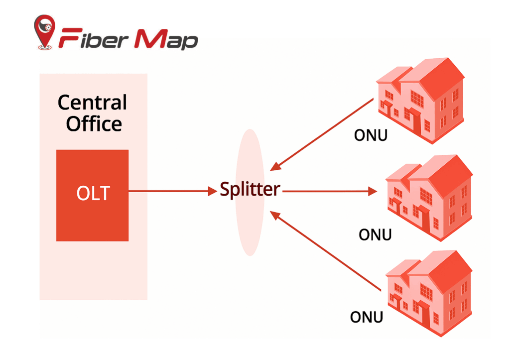
Centralised (single-level) splitting:
- A large splitter (say 1×32 or 1×64) is placed in the central office or head-end.
- From there, one fiber goes out to each subscriber after the split.
- Pros: simpler maintenance, fewer field splice points, easier management.
- Cons: high fiber count from CO to distribution zone, higher initial cabling.
Cascaded (multi-level) splitting:
- First a splitter closer to CO of smaller ratio (e.g., 1×4), then further downstream another splitter (e.g., 1×16) giving overall 1×64.
- Pros: fewer feeder fibers from CO, better for wider geography or less dense zones.
- Cons: more field components, more splicing, potentially higher fault-isolation complexity.
Choosing between them:
- If you’re in a dense urban zone with many subscribers and fiber is plentiful → centralised might win.
- If you’re covering suburban / rural spread or want incremental rollout with lower upfront fiber investment → cascaded might make sense.
3. Split Ratio Design: Balancing Cost, Reach & Quality
The split ratio (for example, 1:32, 1:64) determines how many subscribers share an OLT (Optical Line Terminal) port and has a direct impact on optical budget, signal strength, and future growth.
Key considerations:
- Optical budget: Every splitting action introduces loss. If the ratio is high (many splits) then each subscriber receives less optical power margin.
- Distance / reach: Longer fiber runs + many splits = risk of poor signal margin. In a long-reach rural deployment you may need to use a lower split ratio.
- Subscriber demand / future growth: If you anticipate heavy bandwidth per subscriber (e.g., UHD video, cloud gaming) then lower split ratio might help preserve quality. Conversely, if bandwidth demands are modest you can push the split ratio.
- Economics: Higher split ratio → fewer OLT ports needed → lower cost per subscriber, but must not compromise QoS (Quality of Service).
Rule-of-thumb: In many FTTH deployments a 1:32 or 1:64 split is seen as the “sweet spot” balancing cost & performance.
For very short loops you might push to 1:128 in ultra-dense or future-proof networks (with newer PON standards). But only if you have the optical margin.
4. Putting It All Together: A Deployment Strategy
Here’s a step-by-step logic for your network design:
- Map subscriber density + geography (urban, suburban, rural).
- Determine fiber availability / budget (how many feeder fibers can you afford/pull).
- Select splitter type (PLC vs FBT) based on required ratio and environmental constraints.
- Choose split level architecture (centralised vs cascaded) based on fiber budget + servicing ease.
- Compute optical budget: fiber loss + splitter loss + connector/splice loss + margin. Ensure it meets PON standard specs.
- Choose split ratio by balancing subscriber count per port + signal quality + future growth.
- Document for each zone: splitter location, ratio, feeder fiber count, drop fiber count.
- Monitor installation and maintain reserve capacity (spare ports/fiber) for expansion.
5. Common Mistakes & How to Avoid Them
- Over-splitting without margin: Pushing too high a split ratio just to save cost, but then fiber runs are long or splices many → poor service.
- Ignoring future growth: Not leaving spare ports or fiber for future subscribers can make later upgrades expensive.
- Using wrong splitter type: For large ratios using cheaper FBT may degrade uniformity/stability.
- Not optimizing fiber count in feeder/distribution: In cascaded design you may reduce feeder fiber but ignore extra field complexity.
- Inconsistent connector/termination practices: This creates maintenance headaches and service quality issues. Good design accounts for standard connector types, cleaning procedures etc.
6. Why This Matters for ISPs & Network Planners
For an ISP or service provider rolling out FTTH, these decisions directly impact:
- Capital expenditure (how many OLT ports, how much fiber, how many splitters)
- Operational expenditure (maintenance, field splicing, fault isolation)
- Service quality (subscriber experience, future-proofing)
- ROI timeline (cost per subscriber, upgrade path)
If you get the split level & ratio design right, you’ll build a network that’s efficient today and scalable tomorrow.
Designing FTTH isn’t just “drop fiber to homes and done”. You’ve got to strategically choose how many you split (split ratio), and where you split (split level), in tandem with understanding your geography, subscriber density, fiber budget, and future growth. A thoughtful design means better cost efficiency, easier maintenance, and higher reliability.